


How Wire Gauge and Terminal Control Reduce Heat-Rise Risk in C14-to-C13 Server Rack Power Cords
In data centers and server cabinets, an IEC 60320 C14-to-C13 power cord may look like a simple accessory, yet it often provides a long-term connection between a rack PDU and servers, switches, or storage equipment. If purchasing decisions focus only on connector shape and price, while overlooking conductor size, terminal crimping, and the completed cord rating, problems may emerge after continuous operation. Typical consequences include connector heat rise, premature insulation aging, equipment restarts, and intermittent power loss that is difficult to diagnose. For OEM projects, Dongguan Kuncan Electronics Co.,Ltd recommends reviewing electrical parameters, mechanical construction, and compliance documents in one specification checklist rather than evaluating them separately.
Why Does Continuous Load Increase the Impact of an Undersized Conductor?
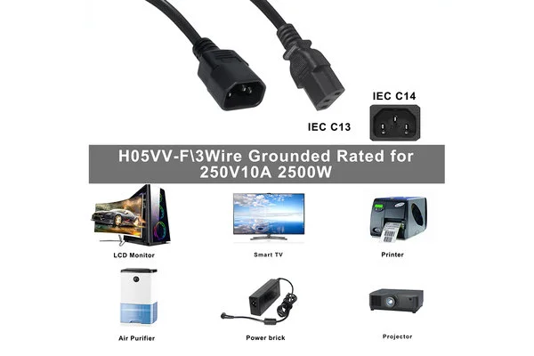
Server equipment may operate for long periods every day, so the cord carries a continuous load rather than only the brief current applied during a basic test. An undersized conductor, excessive cable length, or inconsistent conductor construction can raise circuit resistance and allow heat to accumulate inside the cabinet. For a conventional C14-to-C13 project, 10A at 250V AC can be used as a starting point for specification discussions. A North American configuration may begin with an evaluation of 18/3 SJT, while European projects may consider H05VV-F 3G0.75 mm² or 3G1.0 mm². These values are not universal guarantees; the final selection must reflect equipment current, cable length, ambient temperature, and the rating of the complete cord set.
Wire gauge matters because it directly affects conductor resistance, voltage drop, and temperature rise. A construction that is suitable for a short run at a reasonable load may not remain suitable when the cable is extended. If a buyer standardizes all installations on one longer length while retaining the original conductor size, the result may include greater voltage drop and excess cable stored inside the rack. Coiled or poorly routed cable can also obstruct equipment intake or exhaust airflow. Length customization therefore supports both cleaner cable management and better thermal control.
Why Are Terminal Crimping and Contact Resistance Equally Important?
Correct conductor size alone cannot compensate for an unstable terminal process. An incomplete crimp, loose conductor strands, inconsistent contact dimensions, or contaminated contact surfaces can increase resistance at a localized point. Heat may first develop inside the connector, where it is not immediately visible. When a server begins to restart or loses power intermittently, maintenance teams may spend considerable time checking the PDU, server power supply, and connected cables.
Buyers should ask suppliers to define terminal material, crimping requirements, pull-force controls, and continuity-testing procedures. For volume OEM orders, an approved sample does not automatically prove that mass production will remain consistent. Process controls for strip length, crimp height, and terminal assembly are therefore more informative than a broad claim such as “high-quality copper cable.” These controls provide measurable checkpoints for incoming inspection and supplier-quality management.
How Do Molded Strain Reliefs Reduce Mechanical and Connection Risk?
Cables in high-density cabinets are exposed to bending, pulling, and repeated maintenance activity. Without effective strain relief, mechanical force can transfer directly to the terminals, increasing the likelihood of conductor fatigue, jacket damage, or a loose connection over time. A fully molded C14/C13 connector with an integrated strain-relief section helps distribute bending stress and maintain cable integrity at the connector exit.
However, a standard C13/C14 interface should not be treated as a locking connector. If the installation involves vibration, frequent maintenance, or a significant risk of accidental pulling, the buyer should evaluate a locking C13 option during specification development. Defining this requirement before sampling is more efficient than discovering after installation that an ordinary friction-fit connection does not provide the required retention.
What Should OEM Buyers Verify Before Ordering?
Before order confirmation, buyers should verify the C14 male-to-C13 female orientation, completed cord voltage and current rating, conductor size, cable length, connector temperature class, jacket designation, and target-market approvals. A standard C13/C14 assembly is generally intended for conventional temperature applications and should not automatically replace a C15/C16 configuration required by higher-temperature equipment. For multi-market programs, the model numbers shown in UL/cUL, VDE, CE, or other relevant documentation should match the actual delivered construction. Approval of an individual cable component does not necessarily mean the complete cord set is covered.
Reducing heat-rise and power-loss risk in server racks does not depend on one marketing feature. It depends on the combined suitability of conductor size, cable length, terminal crimping, contact dimensions, strain relief, and compliance documentation. Dongguan Kuncan Electronics Co.,Ltdrecommends that OEM buyers use samples and formal specifications to confirm whether a completed-cord rating of 10A at 250V AC fits the application, and to compare configurations such as 18/3 SJT and H05VV-F 3G0.75–1.0 mm² against the actual load and installation. Matching measurable parameters to the operating environment is the practical way to reduce heat rise, installation rework, and after-sales troubleshooting.


USER EVALUATE
Here is the customer's evaluation of us