


From 6-20P Plug to Open End: Five OEM Checks Before Producing an Inline Ground-Fault Protection Cord
For HVAC systems, pumps, commercial appliances, and industrial equipment, an open-end cord with an inline protection module can reduce field wiring and integrate TEST/RESET functions into the equipment power path. It is not, however, a simple combination of a plug, module, and cable. A mismatch in plug rating, protection circuitry, wire gauge, open-end dimensions, or finished-product approval can cause nuisance trips, reset failures, terminal heating, or failed acceptance. Dongguan Kuncan Electronics Co.,Ltd recommends confirming the following five specifications before sampling and mass production and placing them consistently in the drawing, BOM, label, and inspection documents.
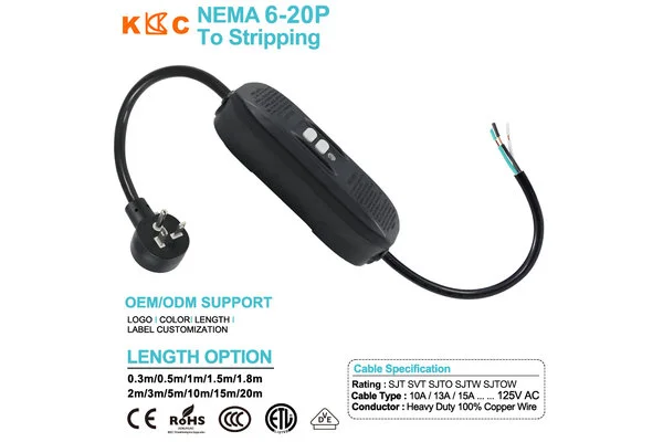
1. Confirm the NEMA 6-20P 20A, 250V Interface
NEMA 6-20P is a 20A, 250V, 2-pole, 3-wire grounding straight-blade plug that normally corresponds to L1, L2, and PE. It differs from the line-neutral-protective-earth arrangement of a 125V circuit, so a three-conductor cable or conductor colors should not be used to copy a 125V product wiring scheme.
The promotional artwork also shows “125V AC, 10A/13A/15A,” which conflicts with the standard 6-20P interface class. Buyers should require the supplier to state whether these values belong to another product-family template and replace generic artwork with documentation for the exact finished model. If the module or cable supports only 15A, the assembly must follow its lowest-rated component and cannot be labeled 20A merely because the plug carries that rating.
2. Confirm the Inline Module for a 250V Line-to-Line Circuit
TEST and RESET buttons show that the module has an operating interface; they do not prove that its internal circuit is suitable for 250V. Purchase documents should identify the manufacturer, exact part number, rated voltage, frequency, maximum current, monitored conductors, switched poles, trip threshold, trip time, manual or automatic reset, and post-power-loss state.
This chain of parameters determines how equipment is de-energized. A module intended only for a 125V circuit, or one that does not interrupt the conductors required by its approved design, can lead to failed functional tests, reset problems, or an unsupported protection claim. The sample must be evaluated as a complete cord on the actual equipment for energization, TEST operation, fault trip, RESET, and power-restoration behavior.
3. Confirm Wire Gauge, Jacket, and Finished Length
If the product is intended for full 20A service, 12 AWG/3C can serve as an engineering baseline. The larger conductor cross-section can help control resistance, voltage drop, and temperature rise under continuous load, but final selection still depends on module rating, cable length, ambient temperature, termination, cable standard, and finished-cord approval.
SJT, SVT, SJTO, SJTW, and SJTOW shown in the artwork should not be treated as freely interchangeable visual options. Buyers should select the jacket against indoor, outdoor, damp, oily, abrasion, and temperature conditions and verify complete cable printing, actual AWG, and conductor material. Length should also be separated into plug-to-module, module-to-open-end, and overall dimensions so that a total-length change does not overlook voltage drop, cable weight, or strain-relief effects.
4. Confirm L1, L2, PE, and Open-End Preparation
The three equipment-side conductors should normally be defined as L1, L2, and PE according to the approved drawing. Conductor color can assist identification but must not be the sole authority for electrical function. The drawing should begin at the NEMA blades, pass through the module input and approved monitoring or interruption path, and continue through the module output to the open leads with a complete point-to-point definition.
The open end also requires separate definitions for outer-jacket removal, individual breakout lengths, strip dimensions, tolerances, and terminal treatment. If ferrules, ring terminals, or sleeves are required, the part number, material, plating, crimp height, and pull requirements should be controlled. Insufficient dimensions can prevent the leads from reaching the terminal block, while excessive length can create enclosure congestion, abrasion, or proximity to hot components.
5. Confirm Testing, Labels, and Finished-Assembly Approval
First-article and production inspection should cover point-to-point continuity, miswire, short-circuit, protective-earth continuity, TEST/RESET operation, and fault-trip testing required by the approved documentation. Depending on the project, dielectric, temperature-rise, pull, flexing, and environmental validation may also be required. Test methods and limits must follow the applicable standard and approved records rather than generic values.
Labels should identify the finished rating, cable type, reset mode, product part number, and necessary warnings. CE, RoHS, CCC, ETL, or other marks shown in promotional artwork do not automatically establish identical approval for every module, gauge, jacket, and length combination. Buyers should verify certificates, reports, label authorization, and batch-traceability documents for the exact configuration.
How Can the Five Checks Become Executable Production Documents?
The engineering drawing defines dimensions and wiring. The BOM locks the plug, module, cable, and terminal part numbers. The control plan establishes tests and sampling. The label file communicates ratings and operating information. Model numbers and revisions must remain consistent across all four documents. Any change to the module, gauge, jacket, length, or terminal should trigger engineering review rather than automatic reuse of a previous approval.
Sample approval should also include assembly and operation on the actual equipment, covering startup, steady state, temperature rise, TEST/RESET, fault operation, and power restoration. If the load includes motors, heating elements, or filters, normal leakage and startup behavior should be evaluated for nuisance tripping rather than masking an application mismatch by changing the trip threshold without approval.
Dongguan Kuncan Electronics Co.,Ltd recommends building the review checklist in the sequence of NEMA interface, protection module, cable, open end, and finished-product approval. Only when these five areas form a closed loop can a NEMA 6-20P inline protected power cord move from sample to repeatable production while helping buyers reduce rating errors, L1/L2/PE miswiring, localized heating, nuisance trips, and after-sales rework.


USER EVALUATE
Here is the customer's evaluation of us